- 您现在的位置:买卖IC网 > Sheet目录322 > DS28DG02E-3C+T (Maxim Integrated)IC EEPROM 2KBIT 2MHZ 28TSSOP
�� �
�
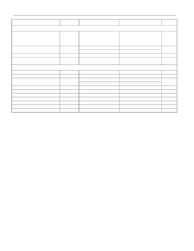
�DS28DG02:� 2Kb� SPI� EEPROM� with� PIO,� RTC,� Reset,� Battery� Monitor,� and� Watchdog�
�PARAMETER�
�SYMBOL�
�CONDITIONS�
�MIN�
�TYP�
�MAX�
�UNITS�
�BATTERY� MONITOR� (See� Figure� 8)�
�V� BAT� Trip� Point�
�V� BAT� Monitor� Trip-Point�
�Tolerance�
�V� BTP�
�V� TRIPTOL�
�Measured� with� V� BAT�
�falling;� trip� point� is� user�
�programmable�
�+25°C�
�-40°C� to� +85°C�
�2.25�
�2.03�
�1.80�
�1.58�
�-1.5�
�-2.5�
�2.31�
�2.08�
�1.85�
�1.62�
�2.38�
�2.14�
�1.90�
�1.66�
�+1.5�
�+2.5�
�V�
�%V� BTP�
�Battery� Test� Load� Current�
�Battery� Test� Duration�
�I� LOAD�
�t� BTPW�
�Load� applied� to� battery�
�(Notes� 5,� 16)�
�7.5�
�2�
�20�
�μA�
�s�
�SPI� INTERFACE� TIMING� (See� Figures� 9,� 10)�
�CSZ� Setup� Time� t� CSS�
�CSZ� Hold� Time� t� CSH�
�(Note� 5)�
�(Note� 5)�
�0.4�
�0.4�
�μs�
�μs�
�CSZ� Standby� Pulse� Width�
�(Note� 5)�
�t� CPH�
�Normal� communication�
�(Note� 17)�
�0.25�
�2.0�
�μs�
�CSZ� to� High-Z� at� SO� t� CHZ�
�SCK� Clock� Frequency� f� CLK�
�0.25�
�2�
�μs�
�MHz�
�Data� Setup� Time� t� DS�
�Data� Hold� Time� t� DH�
�SCK� Rise� Time� t� SCKR�
�SCK� Fall� Time� t� SCKF�
�(Note� 5)�
�(Note� 5)�
�(Note� 5)�
�(Note� 5)�
�50�
�50�
�1�
�1�
�ns�
�ns�
�μs�
�μs�
�Output� Valid� time� t� V�
�(Note� 5)�
�0�
�120�
�ns�
�Note� 1:�
�Note� 2:�
�Note� 3:�
�Note� 4:�
�Note� 5:�
�Note� 6:�
�Note� 7:�
�Note� 8:�
�Note� 9:�
�Note� 10:�
�Note� 11:�
�Note� 12:�
�Note� 13:�
�Note� 14:�
�Note� 15:�
�Note� 16:�
�Note� 17:�
�If� no� battery� is� used,� connect� the� V� BAT� pin� to� V� CC� .� The� RTC� is� powered� by� V� BAT� if� V� CC� falls� below� V� CCmin� .�
�To� the� first� order,� this� current� is� independent� of� the� supply� voltage� value.�
�Nominal� values:� 3.3V� -5%,� set� at� factory.� Measured� with� V� CC� falling;� for� V� CC� rising,� the� actual� threshold� is�
�V� TRIP� +� V� HYST� .�
�This� specification� is� valid� for� each� 16-byte� memory� page.�
�Not� production� tested.� Either� guaranteed� by� design� (GBD)� or� guaranteed� by� a� reliability� study� (EEPROM� lifetime�
�parameters).�
�EEPROM� writes� can� become� nonfunctional� after� the� data-retention� time� is� exceeded.� Long-time� storage� at�
�elevated� temperatures� is� not� recommended;� the� device� can� lose� its� write� capability� after� 10� years� at� +125°C� or� 40�
�years� at� +85°C.�
�Valid� with� 32KHz� crystal,� 12.5pF,� ESR� ?� 45k� ?� ,� +25°C.�
�Total� PIO� sink� and� source� currents� through� all� PIO� pins� must� be� externally� limited� to� less� than� the� absolute�
�maximum� rating� of� 270mA� minus� 1.5mA� for� EEPROM� programming� and� SPI� communication.� Exceeding� the�
�absolute� maximum� rating� can� cause� damage.�
�Assumes� the� configuration� of� the� system� and� the� part� is� such� that� changing� GOV<i>� (0� ≤� i� ≤� 11)� between� ‘b1� and�
�‘b0� switches� between� sourcing� no� current� and� sinking� the� absolute� maximum� current� at� the� PIO<i>� pin.� The� limit�
�refers� to� the� switching� time� between� sinking� 20%� of� the� DC� current� and� 80%� of� the� DC� current.� The� same� is� true�
�for� changing� between� 'b0� and� 'b1� causing� the� part� to� switch� from� sinking� no� current� to� sourcing� the� absolute�
�maximum� current� at� the� PIO<i>� pin.�
�Each� output� pin� transitions� in� 1μs� with� a� pause� of� 1μs� before� the� next� pin� transitions.�
�All� PIO� are� tri-stated� at� beginning� of� reset� prior� to� setting� to� power-on� values.�
�If� the� part� has� battery� power� (normal� case)� the� active� pulldown� of� RSTZ� is� supported� by� the� battery.�
�If� V� BAT� is� tied� to� V� CC� (no� battery� supply)� the� state� of� the� RSTZ� pulldown� transistor� is� not� guaranteed� when� V� CC� falls�
�below� V� POR� .�
�Threshold� refers� to� the� manual� reset� function� obtained� by� forcing� RSTZ� low.�
�Transient� response� to� a� step� on� V� CC� from� above� V� TRIP� down� to� (V� TRIP� -� 1mV).� Glitches� on� V� CC� that� are� shorter� than�
�t� DELmin� are� guaranteed� to� be� suppressed,� regardless� of� their� amplitude.� Glitches� on� V� CC� that� are� longer� than� t� DELmax�
�are� guaranteed� not� to� be� suppressed.� This� parameter� is� tested� at� high� V� CC� and� guaranteed� by� design� at� low.�
�If� enabled,� this� test� takes� place� every� hour� on� the� hour.� The� battery� voltage� is� compared� to� V� BTP� during� the� second�
�half� of� the� t� BTPW� window.� The� timing� is� controlled� by� the� RTC.�
�Extended� duration� applies� to� the� following� cases:�
�1)� Aborted� WREN,� WRDI,� RDSR,� and� WRSR� command.�
�2)� WRITE� command� aborted� before� transmitting� the� first� complete� data� byte� after� command� and� address.�
�3)� READ� command� aborted� before� reading� the� first� complete� data� byte� after� command� and� address.�
�4)� Read� aborted� before� the� end� of� a� byte.�
�4� of� 34�
�发布紧急采购,3分钟左右您将得到回复。
相关PDF资料
DS28E04S-100+T
IC EEPROM 4KBIT 16SOIC
DS28EC20+T
IC EEPROM 20KBIT TO92-3
DS301X
KWIK-CHG DESIGNATION STRIP SGL
DS3030W-100#
IC NVSRAM 256KBIT 100NS 256BGA
DS3045W-100#
IC NVSRAM 1MBIT 100NS 256BGA
DS3050W-100#
IC NVSRAM 4MBIT 100NS 256BGA
DS3065W-100#
IC NVSRAM 8MBIT 100NS 256BGA
DS3065WP-100IND+
IC SRAM 3.3V 8MB 34POWERCAP MOD
相关代理商/技术参数
DS28DG02EVKIT
功能描述:存储器 IC 开发工具 RoHS:否 制造商:STMicroelectronics 产品:Reference Boards 工具用于评估:M24LR64-R 存储容量:64 kbit 存储类型:EEPROM 工作电源电压:1.8 V to 5.5 V
DS28DG02G-3C+
功能描述:电可擦除可编程只读存储器 2Kb SPI 电可擦除可编程只读存储器 w/PIO RTC/Rst/Bat Mtr/Wtdg RoHS:否 制造商:Atmel 存储容量:2 Kbit 组织:256 B x 8 数据保留:100 yr 最大时钟频率:1000 KHz 最大工作电流:6 uA 工作电源电压:1.7 V to 5.5 V 最大工作温度:+ 85 C 安装风格:SMD/SMT 封装 / 箱体:SOIC-8
DS28DG02G-3C+T
功能描述:电可擦除可编程只读存储器 2Kb SPI 电可擦除可编程只读存储器 w/PIO RTC/Rst/Bat Mtr/Wtdg RoHS:否 制造商:Atmel 存储容量:2 Kbit 组织:256 B x 8 数据保留:100 yr 最大时钟频率:1000 KHz 最大工作电流:6 uA 工作电源电压:1.7 V to 5.5 V 最大工作温度:+ 85 C 安装风格:SMD/SMT 封装 / 箱体:SOIC-8
DS28E01-100
制造商:MAXIM 制造商全称:Maxim Integrated Products 功能描述:带SHA-1引擎保护的1K位1-Wire EEPROM
DS28E01-100_12
制造商:MAXIM 制造商全称:Maxim Integrated Products 功能描述:1Kb Protected 1-Wire EEPROM with SHA-1 Engine
DS28E01-100+
功能描述:电可擦除可编程只读存储器 RoHS:否 制造商:Atmel 存储容量:2 Kbit 组织:256 B x 8 数据保留:100 yr 最大时钟频率:1000 KHz 最大工作电流:6 uA 工作电源电压:1.7 V to 5.5 V 最大工作温度:+ 85 C 安装风格:SMD/SMT 封装 / 箱体:SOIC-8
DS28E01G-100+R
制造商:DALLAS 制造商全称:Dallas Semiconductor 功能描述:1K-Bit Protected 1-Wire EEPROM with SHA-1 Engine
DS28E01G-100+T
制造商:DALLAS 制造商全称:Dallas Semiconductor 功能描述:1K-Bit Protected 1-Wire EEPROM with SHA-1 Engine